Voltage Controlled Oscillator (VCO)
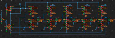
This work compares the performance of three different VCO circuits, namely: variable resistor and varactor based. Below are the results of Cadence simulations done at different corners.
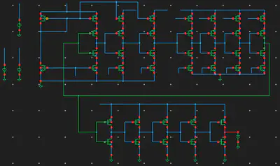
Variable resistor based circuit:
- SS corner:
$f_{min}$ = 4.18 MHz, $f_{max}$ = 1.25 GHz, $P$ = 2.33 mW, $K_{VCO}$ = 23.56 GHz/V
- FF corner:
$f_{min}$ = 32.67 MHz, $f_{max}$ = 1.95 GHz, $P$ = 2.29 mW, $K_{VCO}$ = 28.73 GHz/V
- SS corner:
$f_{min}$ = 1.41 GHz, $f_{max}$ = 2.60 GHz, $P$ = 1.86 mW, $K_{VCO}$ = 15.67 GHz/V
- FF corner:
$f_{min}$ = 1.92 GHz, $f_{max}$ = 3.79 GHz, $P$ = 2.66 mW, $K_{VCO}$ = 22.60 GHz/V
Overall, it can be seen that they both have their own advantages and disadvantages and the choice of which device to use depends on the application (e.g. for low power devices varactors are preferred).
Dias Azhigulov
Master student in Electrical and Computer Engineering
I find joy in learning about computers & related technologies both on software and hardware level.